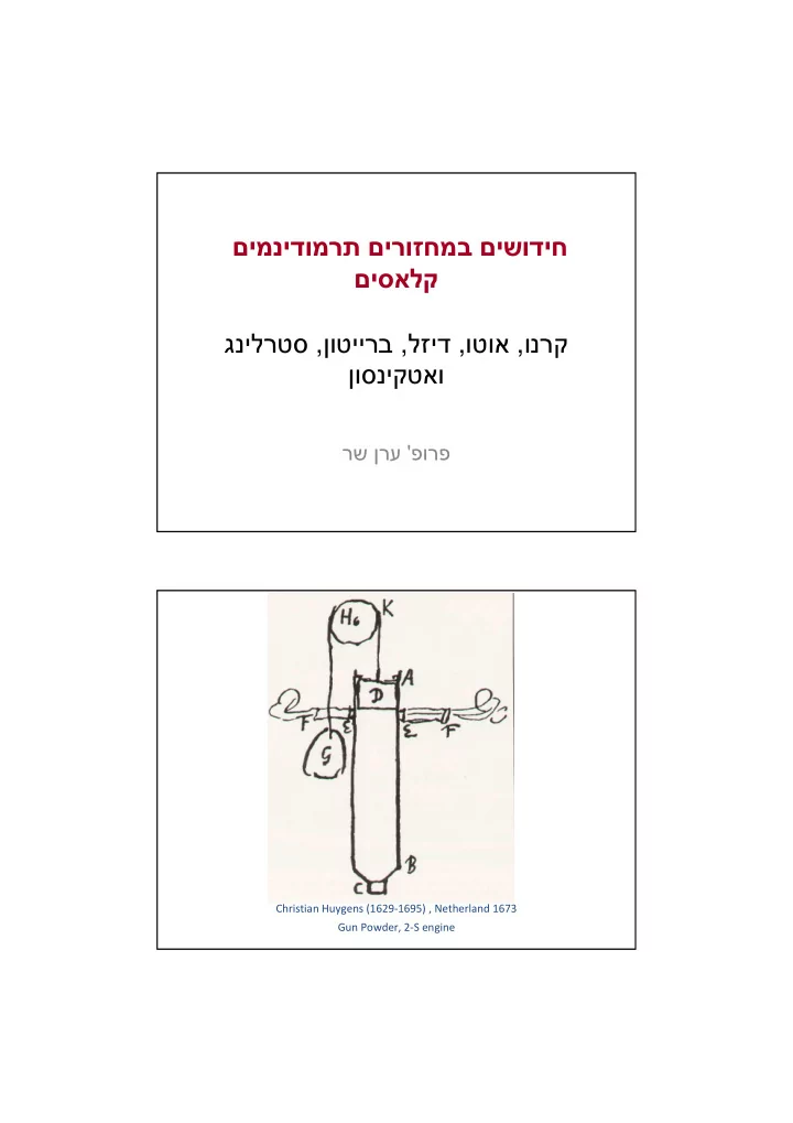

םימנידומרת םירוזחמב םישודיח םיסאלק ונרק , וטוא , לזיד , ןוטיירב , גנילרטס ןוסניקטאו פורפ ' רש ןרע Huygens Christian Huygens (1629-1695) , Netherland 1673 Gun Powder, 2-S engine
Cugnot Nicolas Joseph Cugnot (1725-1804) , France 1795 Coal and Steam Otto Nicolaus August Otto (1832-1891) , Germany 1867 Gasoline 4-S
Otto ( ) − mc T − T Q Q Q 4 1 H L L v η = = 1 − = 1 − th ( ) − Q Q mc T T 3 2 H H v ( ) / − 1 T T T 1 4 1 η = 1 − th ( ) / 1 T T T − 2 3 2 k − 1 k − 1 T V V T 2 1 4 3 = = = T V V T 1 2 3 4 1 T 1 1 1 η = − = − th k − 1 T r 2 v Real indicator diagram Actual vs. Ideal Otto cycle � Slow combustion process � Incomplete combustion process � Heat losses during combustion and expansion � Low c p / c v ratio � Exhaust blow-down � Pumping losses
Delay & combustion duration [ ] 1 / 3 2 / 3 [ ] 1 / 3 2 / 3 − − ~ ~ ∆ θ CA N S ∆ θ CA N S d L b L For Stoichiometric mixture: − 0 . 16 2 . 18 p T ( ) = 1 − 2 . 1 S S f L L , 0 p T 0 0 ~0.4m/s for STP Spark Knocking-1 Self ignition BTC ATC Auto-ignition Detonation
Actual cycles-3 � Correct fuel metering � Incomplete combustion � Small and uniform fuel droplets process (high bsfc and emission) � Good mixing � Low c p / c v ratio � Alternative fuel / oxidant � Inlet valve timing � Pumping losses � Wide ports Engine losses
Stirling Engine-1 Q H p T 3 3 4 η = η Stirling Carnot Q 2 4 2 1 Q L 1 v s ( ) ( ) ( ) ( ) ln / ln / Q − Q mT s − s − mT s − s T R V V − T R V V T 3 4 3 1 2 1 3 4 3 1 2 1 1 H L η = = = = 1 − Stirling ( ) ( ) ln / Q mT s − s T R V V T 3 4 3 3 4 3 3 H Wankel Engine-2 Intake Compression Exhaust Intake Exhaust Expansion Spark
Stirling Engine-2 1 2 3 4 Catalyst Main Drawbacks � Under fuel-rich conditions Poor CO and HC conversion � Under fuel-lean conditions Poor NOx conversion � Under low temperature Poor conversion efficiency � Under high temperature Fast thermal aging � Deposits: its efficiency is highly sensitive to deposits � Back pressure: Constitutes a high back pressure � Recycling is a problematic issue
Diesel 8000 ( ) 2 3 Q − Q Q mc T − T H L L v 4 1 1 1 η = = − = − Diesel cycle th ( ) 7000 − Q Q mc T T 3 2 H H p r s =2.2 ( ) / 1 6000 T c T T − 1 v 4 1 η = 1 − th r s =3.0 ( ) Pressure [kPa] / − 1 T c T T 2 3 2 p 5000 V V T 3 3 1 = = = r and r v s V V T 4000 2 2 2 Otto cycle k − 1 k − 1 T T T T V V V 3000 4 4 3 2 3 2 1 k = = r = r s s T T T T V V V 1 3 2 1 2 4 2 s=const. 2000 s=const. 1000 4 1/8.5 1 0 0 0.2 0.4 0.6 0.8 1 1.2 V/V 1/22 max k 1 1 r − s 1 η = − th ( ) 1 k − − 1 k r r s v Turbocharger
Compressor Map
Recommend
More recommend