Generalized Force Directed Relaxation with Optimal Regions and Its - PowerPoint PPT Presentation
Generalized Force Directed Relaxation with Optimal Regions and Its Applications to Circuit Placement: A Tribute to Professor Satoshi Goto Yao-Wen Chang ywchang@ntu.edu.tw National Taiwan University March 21, 2017 1 Goto Force Directed
Generalized Force Directed Relaxation with Optimal Regions and Its Applications to Circuit Placement: A Tribute to Professor Satoshi Goto Yao-Wen Chang ywchang@ntu.edu.tw National Taiwan University March 21, 2017 1
Goto Force Directed Relaxation with Optimal Regions and Its Applications to Circuit Placement: A Tribute to Professor Satoshi Goto Yao-Wen Chang ywchang@ntu.edu.tw National Taiwan University March 21, 2017 2
The Milestone Paper 3
Outline Placement Basics Placement Basics Prof. Goto’s 1981 Milestone Work Applications to Modern Placement Future Research Directions 4
Circuit Placementb ● Place objects into a die s.t. no objects overlap with each other & some cost metric (e.g., wirelength) is optimized chip ISPD98 ibm01 12,752 cells 842K cells 247 macros 646 macros A max /A min = 8416 868K nets wirings among modules (cells/macros) are not shown here!! 5
Placement Algorithm Paradigms ● Constructive algorithm: Places a module at a desired position and fix its position. Cluster growth, min cut, QP, etc. ● Iterative algorithm: Modifies a placement to improve its solution quality until some termination condition is met. Force-directed method, nonlinear placement, etc ● Nondeterministic approach: Applies a probabilistic model to determine the placement process Simulated annealing, genetic algorithm, etc. Constructive Iterative Nondeterministic Improvement refinement Initial solution could combine multiple elements 6
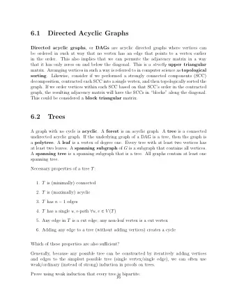
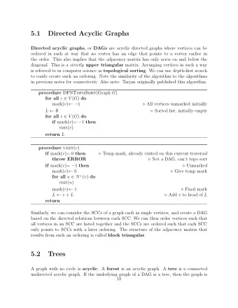
Outline Placement Basics Prof. Goto’s 1981 Milestone Work Applications to Modern Placement Future Research Directions 7
Prof. Goto’s 1981 Milestone Work ● Goto , “An efficient algorithm for the two -dimensional placement problem in electrical circuit layout,” IEEE TCAS, Jan. 1981. SORG • Sub-Optimal Random Generation (SORG) • Sequentially selects unplaced modules (constructive based on their connectivity to other initial modules and places them in their optimal regions to minimize the total wirelength. placement) GFDR • Goto Force-Directed Relaxation (GFDR) • Repeatedly interchanges a set of modules (iterative in optimal or near-optimal regions to improvement) minimize the total wirelength 8
Optimal Region [Goto 1981] 6 6 ● Objective : min ( 𝑗=1 𝑦 1,𝑗 + 𝑗=1 𝑦 1 − 𝑧 1 − 𝑧 1,𝑗 ) ● Module m ’s optimal region is formed by the medians of the boundaries of its net bounding boxes (excluding m ) 𝑧 1,1 𝑓 1,2 𝑓 1,1 𝑧 1,2 𝒏 𝑧 1,3 Optimal medians region 𝑧 1,4 𝑧 1,5 𝑧 1,6 𝑓 1,3 𝑦 1,1 𝑦 1,2 𝑦 1,3 𝑦 1,4 𝑦 1,5 𝑦 1,6 medians [FastPlace, NTUplace] 9
Optimal Region [Goto 1981] 6 6 ● Objective : min ( 𝑗=1 𝑦 1,𝑗 + 𝑗=1 𝑦 1 − 𝑧 1 − 𝑧 1,𝑗 ) ● Module m ’s optimal region is formed by the medians of the boundaries of its net bounding boxes (excluding m ) 𝑧 1,1 𝑓 1,2 𝑓 1,1 𝑧 1,2 𝒏 𝑧 1,3 Optimal medians region 𝑧 1,4 𝑧 1,5 𝑧 1,6 𝑓 1,3 𝑦 1,1 𝑦 1,2 𝑦 1,3 𝑦 1,4 𝑦 1,5 𝑦 1,6 medians [FastPlace, NTUplace] 10
Goto Force-Directed Relaxation [Goto 1981] ● Repeatedly interchanges modules to minimize wirelength ● Compute the optimal region for a module, fixing all others ● 𝜗 -neighbor( m ): Modules with the Manhattan distance ≤ 𝜗 to A module m ’s optimal location C ● For a module m , G FDR computes m ’s 𝜗 -neighbors; for F D B each m ’s 𝜗 -neighbor, G FDR E H further computes its 𝜗 -neighbors, etc. until 𝜇 modules are identified K G I ● Select the 𝜇 module exchange J sequence with the minimum total wirelength, if any. 1-neighbor, 3-exchange sequence: 𝐵 → 𝐶 → 𝐻 → 𝐵 𝐵 → 𝐶 → 𝐿 → 𝐵 , etc. 11
Outline Placement Basics Prof. Goto’s 1981 Milestone Work Applications to Modern Placement Future Research Directions 12
Typical Modern Circuit Placement Flow ․ Chen, et al., “A high quality analytical placer considering preplaced blocks and density constraint,“ ICCAD -06 (TCAD-08) Computes the best position Global Placement for each module to minimize (GP) the cost (e.g., wirelength), ignoring module overlaps Places modules into row Legalization and removes all overlaps (LG) among modules Detailed Placement Refines the solution (DP) 13
Placement with Density Constraint ● Given a chip region and module dimensions, divide the placement region into bins ● Determine (x, y) for all movable modules min W(x, y) // wirelength function 1. Density b (x, y) ≤ MaximumDensity b s.t. for each bin b 2 . No overlap between modules A module Density = bins A bin 14
Multilevel Global Placement Cluster the modules based on Iteratively decluster the connectivity/size to reduce clusters and further the problem size. refine the placement Initial placement declustering & refinement clustering declustering clustering & refinement clustered module chip boundary 15
mPL: GFDR for Multilevel Refinement [ICCAD-05] ● Chan et al., “Multilevel optimization for large -scale circuit placement,” ICCAD -05 ● For a module, extended G FDR A computes its 𝜗 -neighbors and randomly selects one to further C compute the new 𝜗 -neighbors, F D B until 𝜇 modules are identified ● Extended G FDR tries all module E H permutations in the sequence to K I G find the best placement ● Six 3-exchange sequence: J no exchange, 𝐵 ↔ 𝐶, 𝐵 ↔ 𝐻, All six 3-exchange 𝐶 ↔ 𝐻, 𝐵 → 𝐶 → 𝐻 → 𝐵, sequences are explored 𝐵 → 𝐻 → 𝐶 → 𝐵 . 16
Minimum Implant Area (MIA) Constraint ● Different VT cells can be fabricated by controlling the dopant concentration during ion implantation ● A low or high VT cell may violate the minimum implant area (MIA) constraint if its PMOS or NMOS implant area is too small Implant area > Implant area < MIA constraint MIA constraint MIA MIA Dopant Vdd Vss Vdd Well Vss Ion implantation Violations OK ● If cell height is uniform: MIA constraint minimum cell width constraint 17
Cell Abutting for Solving MIA Constraints ● Could insert fillers to cells to make a bigger implant area ● Abutting violating cells of the same VT could lead to smaller area overhead than filler insertion alone Bigger area!! Violating 𝑑 1 𝑑 2 𝑑 3 cells MIA 𝑑 4 𝑑 5 𝑑 6 𝑑 1 𝑑 2 𝑑 3 𝑑 7 𝑑 8 𝑑 4 𝑑 5 𝑑 6 Filler insertion 𝑑 7 𝑑 8 Smaller area!! 𝑑 1 𝑑 2 𝑑 5 Initial placement 𝑑 4 𝑑 3 𝑑 6 𝑑 7 𝑑 8 Cell abutting 18
NTUplace: MIA-Aware Placement [DAC-16] ● Tseng, Chang, and Liu, “Minimum -implant-area-aware detailed placement with spacing constraints,” DAC -16. ● Transform an MIA-violating placement to a cluster-based placement and solve it by traditional placement methods Violating cells Framework 𝑑 1 𝑑 2 𝑑 3 𝑑 4 MIA-violating 𝑑 5 𝑑 6 𝑑 7 𝑑 8 𝑑 9 placement 𝑑 10 𝑑 11 𝑑 12 𝑑 14 MIA-violating placement Clustering Clusters 𝑑 1 𝑑 3 𝑑 4 𝑑 9 𝑑 5 𝑑 7 𝑑 8 𝑑 2 Traditional placement 𝑑 10 𝑑 6 𝑑 11 𝑑 12 𝑑 14 Cluster-based placement 19
Optimal Region (OR) Based Clustering ● Cluster violating cells of the same VT in their ORs Minimize wirelength while satisfying the MIA constraint 6 6 ● OR for a cell: min ( 𝑗=1 𝑦 1,𝑗 + 𝑗=1 𝑦 1 − 𝑧 1 − 𝑧 1,𝑗 ) ● OR for a 2-cell cluster with 𝑛 𝑗 nets connecting to cell 𝑑 𝑗 2𝑛 1 𝑦 1 − 2𝑛 1 𝑧 1 − 2𝑛 2 𝑦 2 − 2𝑛 2 𝑧 2 − min ( 𝑗=1 𝑦 1,𝑗 + 𝑗=1 𝑧 1,𝑗 + 𝑗=1 𝑦 2,𝑗 + 𝑗=1 𝑧 2,𝑗 ) 𝑧 1,1 𝑓 1,2 𝑑 1 𝑑 2 𝑓 1,1 𝑧 1,2 2-cell cluster 𝒅 𝟐 𝑧 1,3 Optimal medians region 𝑧 1,4 𝑧 1,5 𝑧 1,6 𝑓 1,3 𝑦 1,1 𝑦 1,2 𝑦 1,3 𝑦 1,4 𝑦 1,5 𝑦 1,6 medians 20
Partial Layouts (2.5%): Ours vs. Baseline ● Circuit: mgc_pci_bridge32_1 ● MIA: 10 site steps; LVT: 10%, HVT: 10% ● Area: 14.5% smaller Area overhead!! ● Wirelength: 30.4% shorter Ours Baseline 21
FastPlace/POLAR: [ISPD-05/ICCAD-13] ● Lin, Chu, Shinnerl, Bustany, and Nedelchev , “POLAR: Placement based on novel rough legalization and refinement ,” ICCAD-13. ● Fixing all other modules, an unlocked module can be moved to its optimal region if the target bin has enough unlocked modules to balance density. Two move chains new module position after Original module position movement and move chains 22
Outline Placement Basics Prof. Goto’s 1981 Milestone Work Applications to Modern Placement Future Research Directions 23
Future Placement Challenges Multi-dimension Scalability Heterogeneity Technology 24
Modern Placement Challenges ․ High complexity 10M+ placeable Tens of millions of modules modules to be placed mixed-size ․ Placement constraints design Preplaced modules Chip density, etc. 1000+ macros ․ Mixed-size placement SoC design Hundreds/thousands of large macros with millions of small 3D IC standard cells FinFET ․ Many more TSV 3D IC Analog, etc. substrate 25
Recommend


More recommend
Explore More Topics
Stay informed with curated content and fresh updates.