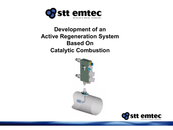

Development of an Active Regeneration System Based On Catalytic Combustion
Active regeneration Based on secondary fuel injection and catalytic combustion Soot oxidation rate 400 60 Soot Oxidation Rate (g/hr) 350 4.8 g/L 50 Soot Oxidation Rate 300 2.4 g/L 40 250 0.6 g/L (g/hr) 30 200 150 20 100 10 50 0 0 150 200 250 300 350 400 450 600 620 640 660 680 DPF Inlet Temperature (°C) Inlet Temperature (°C) NO2 Regeneration O2 Regeneration 2NO2+C => 2NO +CO2 O2+C => CO2
Active regeneration Based on secondary fuel injection and catalytic combustion Fuel consumption 500 150 kg/hr 150 700 kg/hr Expected Temp Increase 400 120 1200 kg/hr Power output (kW) 300 90 (°C) 200 60 100 30 0 0 0 25 50 75 100 125 0 50 100 150 200 250 Power output (kW ) Fuel Injection Rate (cm3/min )
Active regeneration system System description - Based on secondary fuel injection - Catalytic combustion - Controlled Regeneration - Ensures required Soot oxidation Rates.
Active regeneration system Main components - Fuel supply - Injection manifold - Electronic control unit
Control Algorithm Regeneration start parameters • Max soot loading is reached. • And/or min. regeneration time interval reached. • Acceptable exhaust temperature
Control Algorithm Regeneration stop parameters • Injection time has elapsed. • Engine switched off. • Temperature after catalyst under low limit over time. • Temperature after catalyst over high limit. • System error.
Active regeneration system Field trial
System description Injection manifold / Dosing unit Combustion catalyst Fuel delivery system DPF
Field trial results Example of regeneration event Fuel pressure Air pressure After catalyst Before DPF After DPF Exhaust pipe Before catalyst Engine speed Engine load
Field trial results Example with regeneration triggered by exhaust back pressure Before catalyst After catalyst Temperatures Exhaust back pressure 140 mbar
Field trial results DPF performance • Low temperature application • High PM application • Controlled regeneration • Succesful regeneration • Clean tailpipe
Safety features Control system safety functions • Injection, air pressure and fuel pressure stop at system error. • System error at high catalyst outlet temp • System error at hi/lo Fuel and air pressure. • System error at Injection (PWM) feed back error. • System error at EGR error (if used) • Fuel pressure only in injection mode
Recommend
More recommend