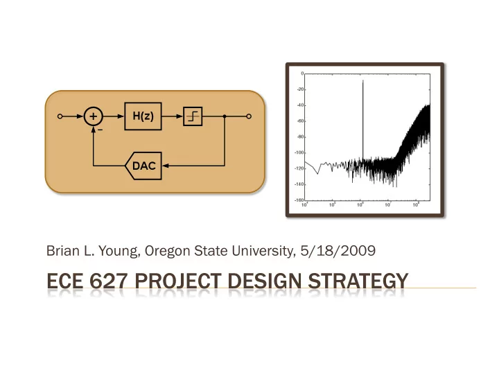

Brian L. Young, Oregon State University, 5/18/2009
Software Tools Preliminary Calculations Mathematical Design Script, MATLAB Simulink Modeling Circuit Implementation Simulink Results Suggestions 2
MATLAB/Simulink Delta Sigma Toolbox (MATLAB) http://www.mathworks.com/matlabcentral/ fileexchange/19 SD Toolbox 2 (Simulink) http://www.mathworks.com/matlabcentral/ fileexchange/7589 Cadence/Spectre SWITCAP (“sw2” on SunOS machine) 3
Panic for 5 seconds… Now, Stop Panicking Examine Requirements ENOB, F BW , F S , etc. Determine Target Technology Same as ECE 626? Explore DStoolbox Demos dsdemo[1-3,5].m 4
Calculate SQNR Modulator Order, OSR, Quantizer Levels Power efficient designs thermal noise limited, quantization noise limited 5
Compare Modulator Order vs. OSR vs. Quantizer Resolution 1-b -bit [Schr hreier a and nd Teme mes, 2 , 2005] 2-b -bit 3-b -bit 6
Consider ΔΣ Topologies Single Loop vs. MASH; CIFB, CIFF, CRFB, CRFF, etc. Write MATLAB script to optimize coefficients Order, OSR, Bits, ǁ‗ H ǁ‗ ∞ , etc. DStoolbox dsdemo[1-3].m 7
Modulator Coefficients NTF and STF Magnitude Poles and Zeros Time-domain Simulation Results 8
Refer to dsdemo3.m scaleABCD( , , , [x [x 1 , … , …, , x L ], , , ) xlim = [x 1 , …, x L ] Iteratively adjust values of xlim to change [a, b, c, g] coefficients Examine [a, b, c, g] coefficients for integer ratio quantization Eases switched-capacitor integrator ratios, and matching 9
Maximize State Amplitude to minimize distortion Leave some margin 10
MATLAB fdatool Multirate filter (CIC Decimator) Design Post Filter Quantize Coeff. Fixed-point Math Export to Script or Simulink 11
Real Integrator Use as starting point Finite Gain Noise Sources Gain Bandwidth kT/C Noise Slew Rate White Noise 12
Finite Gain & BW, SR Digital Round-off Errors DAC & Cap Mismatch Create MATLAB script to control Simulink model Analog Noise 13
Initialize variables in MATLAB script Choose “Accelerator” to speedup simulation Must have C/C++ Configuration Parameters Solver options variable step, discrete (no continuous states) 14
15
Folding of quantization error Shifts NTF zero locations 16
Based on max integrator step size Abrupt impact on integrator settling Interdependence with GBW 17
Can cause increased in-band quantization noise GBW of the order of F S Interdependence with Slew Rate 18
Examine dsdemo5.m Mismatch causes distortion DWA high-pass filters mismatch 19
MATLAB fdatool Quantize Coeff. Internal Precision Output Fraction Bits Code into MATLAB Easier Testing 20
Includes non-ideal effects DWA active (8-bit matching) Average of 32 runs, 2 16 points Initialize Integrator States Randomly 21
PSD of Decimated and Filtered Output F BW = 20 MHz 22
Start Early! Understand DStoolbox dsdemo’s Write DStoolbox Script Fully test before starting Simulink and Cadence!!! Build Transistor-based Switches in Cadence Helps mitigate convergence issues Understand SD Toolbox 2 (Simulink) and adapt to your system 23
Recommend
More recommend