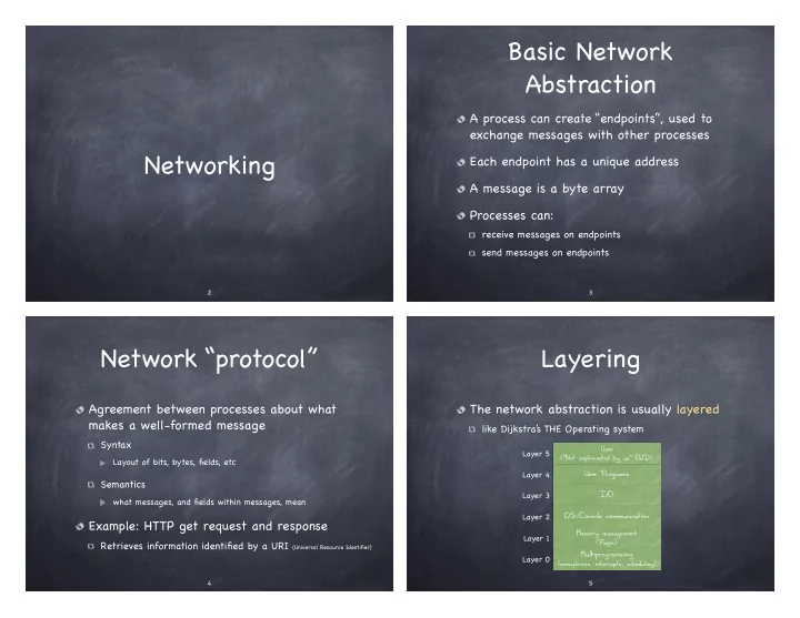

Basic Network Abstraction A process can create “endpoints”, used to exchange messages with other processes Networking Each endpoint has a unique address A message is a byte array Processes can: receive messages on endpoints send messages on endpoints � 2 � 3 Network “protocol” Layering Agreement between processes about what The network abstraction is usually layered makes a well-formed message like Dijkstra’ s THE Operating system Syntax User Layer 5 (“Not implemented by us” EWD) Layout of bits, bytes, fields, etc Layer 4 User Programs Semantics Layer 3 I/O what messages, and fields within messages, mean Layer 2 OS-Console communication Example: HTTP get request and response Memory management Layer 1 Retrieves information identified by a URI (Universal Resource Identifier) (Pager) Multiprogramming Layer 0 (semaphores, interrupts, scheduling) � 4 � 5
Layers support Network Layering Modularity Each layer The network abstraction is usually layered relies on services from layer below Application exports services to layer above Presentation Interfaces between layers Application Session Hide implementation details Transport Transport Network Ease maintenance, updates Network Link Link changes in the implementation of layer’ s service are transparent to the rest of the system Physical Physical Actual 5-Layer Proposed 7-Layer Internet Protocols Stack ISO/OSI Reference Model (1970s) � 6 � 7 OSI Layers Internet Protocol Stack Application User interface tasked for displaying received info to the user Application Exchanges messages HTTP, FTP, DNS Translation between network and application formats, Presentation encryption, compression Transports messages; Transport TCP, UDP Exchanges segments Session Connection management; synchronization, checkpointing Transports segments; Data transfer, reliability, packetization, retransmission. Transport Network IP, ICMP (ping) exchanges datagrams Lets multiple apps share one network connection Path determination across multiple network segments, Network Transports datagrams; routing, logical addressing. Link Ethernet, WiFi Exchanges frames Decides whose turn it is to talk, Link finds physical device on network. Transport frames; Wires, signal Physical Physical Exchanges bits on the media (electrical, optical, etc.) exchanges bits encoding � 8 � 9
How a network Who does what? looks like App App Application HTTP, FTP, DNS Transport TCP, UDP OS Network IP. ICMP (ping) CPU Memory Link Ethernet, WiFi Bus wires, Physical Controller signal encoding NIC Physical Transmission Routers Each host has one or more Network Interface Cards (NICs) Switches Attached to host’ s system buses WiFi Routers Combination of hardware, software, firmware Endpoints � 10 � 11 The Big Picture The Big Picture messages messages Application Application Application Application segments Ports (http: 80; DNS: 53; Telnet: 23) segments Transport Transport Transport Transport datagrams IP addresses (192.168.100.254) datagrams Network Network Network Network Network Network or packets or packets MAC addresses (00:12:F4:AB:0C:82) frames frames Data Link Data Link Data Link Data Link Data Link Data Link bits bits Physical Physical Physical Physical Physical Physical � 12 � 13
Recommend
More recommend