1.101: Introduction to CEE Design Introduction to Shop Drawings - PowerPoint PPT Presentation
1.101: Introduction to CEE Design Introduction to Shop Drawings September 9, 2015 Purpose of a Drawing Convey information Aid in design process Documentation Types of Drawings Working (design) sketch Presentation figure
1.101: Introduction to CEE Design Introduction to Shop Drawings September 9, 2015
Purpose of a Drawing Convey information Aid in design process Documentation
Types of Drawings Working (design) sketch Presentation figure Engineering (shop) drawing
Working Sketches Aid in conceptual design Usually hand-drawn Pertinent dimensions included
Presentation Figures Convey design concepts May be hand drawn or computer generated May be 2-D or 3-D May display key dimensions May display part labels and other text
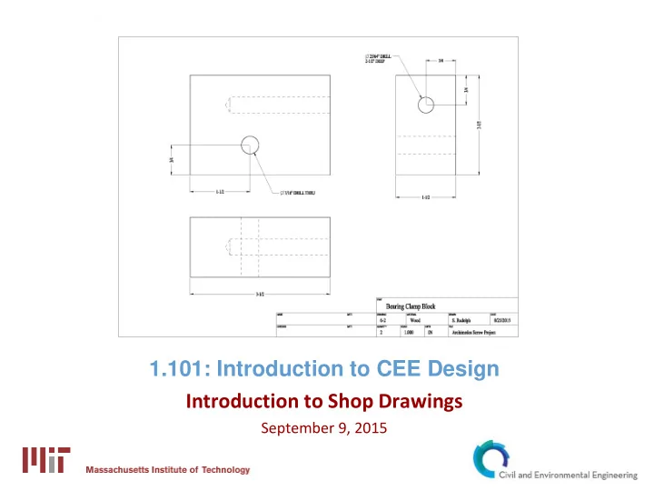
Shop Drawings Intended to convey all information necessary to manufacture a part or assembly Should include: One or more views of the part Dimensions Details and notes Drawing and part information Drawing name Date Draftsperson Units of measure Scale Quantity Material
Shop Drawings: Views A drawing will contain at least one view of the part Typically two or three views are shown Views are usually 2-D views A 3-D view (usually isometric) may be included for conceptualization 2-D views are usually orthographic (drawn at right angles) Orthographic views are most commonly arranged using Third Angle Projection Handouts: Projection Block, Fold Example
Shop Drawings: Line Styles Help to clarify views of a part Differentiate between part and dimensions
Shop Drawings: Symbols Adds information to a dimension Aids in describing a feature (such as a hole) Common drawing symbols: R = radius Ø = diameter THRU = feature extends “through” the part DEEP = depth of a hole or feature
Shop Drawings: Basics The most important aspect of a drawing is clarity Witness lines should extend to features All features require an X and a Y dimension Holes are dimensioned to center Dimensions and details should not reference hidden features Leave gaps between features and witness lines
Computer Aided Design (CAD) Software available through IS&T AutoCAD (Autodesk Suite) SolidWorks Software available through CEE KeyCreator
Recommend


More recommend
Explore More Topics
Stay informed with curated content and fresh updates.